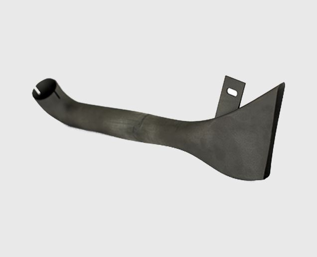
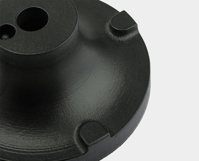
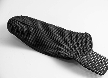
Multi Jet Fusion (MJF)

Discover the new technology that is ideal for when you need short lead times, low porosity, and excellent surface quality for functional prototypes and small series.

MJF 3D Printing

Powder-based 3D Printing without Laser

Multi Jet Fusion uses fine-grained materials that allows for ultra-thin layers of 80 microns. This leads to parts with high density and low porosity, compared to parts produced with Laser Sintering. It also leads to an exceptionally smooth surface straight out of the printer, and functional parts need minimal post-production finishing. That means short lead times, ideal for functional prototypes and small series of end-parts.

  • Low Volume Production
  • Prototypes with mechanical properties to rival those of injection-molded parts
  • Economical production of unique, complex designs built as one-off products or in small batches
  • Lightweight designs using complex lattice structures

Have any Questions or Suggestions? We would love to help you!

Technical Specification

Maximum Build Volume

Dimensional Accuracy

Minimum Wall Thickness

Surface Structure

MJF Materials

Multi Jet Fusion - VoxelWerks

Nylon PA-12

Polyamide
High Density and Low Porosity
Water Resistance

SLS 3D Printing

Ready to get started on your MJF 3D Printing Quote?

Free shipping on all 3D printing orders*

Applications for HP Multi Jet Fusion 3D Printing

Concept Models

The speed and versatility of MJF let product developers create tough and detailed physical snapshots of their designs.
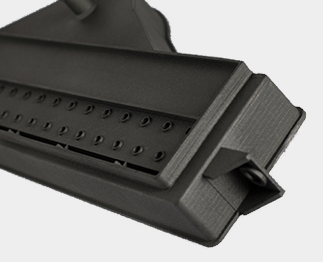
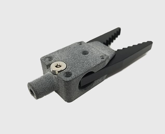
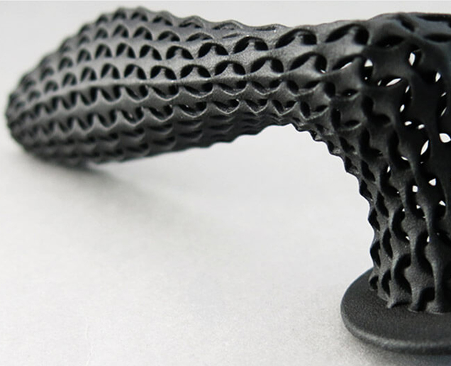
Rapid Prototyping

MJF can be used to create fully-functional prototypes, complete with moving parts, as well as all-in-one assemblies.

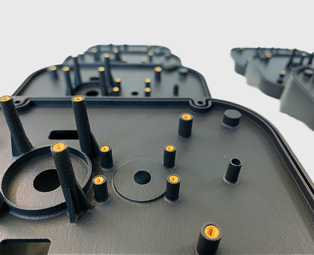
Direct Digital Manufacturing

The low price and speed of Multi Jet Fusion make it an ideal way to build large quantities of discrete or customized parts.

Have any Questions or Suggestions? We would love to help you!

MJF Design Guidelines

Wall Tickness

In 3D printing, wall thickness refers to the distance between one surface of your part and the opposite sheer surface. For PA 12, we recommend a minimum wall thickness of 1 mm but living hinges are possible at 0.3 mm. High wall thickness can give you a strong solid surface, while lower wall thickness can create a flexible and expandable surface. For example, thin surface walls are ideal when designing a spring that needs some suspension properties. This makes your part light and flexible. The opposite effect can be achieved by making your surface walls thicker.

Hollowing

If possible, try to hollow out your part. This avoids deformation and discoloration during the printing process. You can either hollow out your part without a surface hole, which means that unsintered powder will remain trapped inside, or you can design a strategically placed hole (two would be even better) so that the unsintered powder can be easily removed after printing. If the part needs to be reclosed, design a lid with a diameter allowing for 0.5 mm play between the part and the lid.

If your part has walls thicker than 9 mm, our production team may hollow out the part to prevent deformation and discoloration. For parts with wall thickness higher than 20 mm wall thickness, this is done by default. In that case, the powder will stay trapped inside.

Warpage and Deformities

We strongly recommend that you do not design large, flat plains in dimensions like an A4 page. In most cases, your model will deform. This process is called “warping”. Even if you create support ribs under your plane, it doesn’t solve the problem. It increases the chance of deformation even more. The key here is to avoid big flat planes.

Interlocking or Moving Parts

It is possible to print interlocking and moving parts or single-build assemblies in PA 12 (MJF). Parts that are printed together should have a minimum clearance of 0.5 – 0.6 mm. If you want to print a chain, spacing between your surfaces is crucial. The more space you can afford the better. The more complex your part is, the more difficult it becomes for us to evacuate un-sintered powder from the interior when the part is taken out of the 3D printer. Please get in touch with your local Customer Support Officer first before ordering parts of this kind to ensure printability and avoid disappointments.

Assembly

When designing parts that need to be assembled, it’s important to maintain enough distance between the parts. A perfect fit in your CAD software does not necessarily ensure a perfect fit after printing because your software ignores the friction present in the real world. Therefore, always leave at least 0.6 mm between the different parts. For parts with large surfaces and wall thicknesses, you will need to maintain even more distance between the parts. In cases like these, please contact your local Customer Support Officer to check printability.

In order to help us print your parts with the best possible dimensions for assembly, please design your files with an orientation equal to the relative orientation of your parts in the final assembly.

Strength and Fragility

Several factors make it hard to fully predict the outcome of the polishing process. One of them is the geometry of your part, which can act differently each time it is put in the tumbler. In general, you should have wall thicknesses of at least 1 mm throughout your part. Although we carefully place and orientate your parts in our printers to minimize “weak points” created by the layered buildup of your part, certain elements of your design may be more sensitive to the impacts of the polishing stones than others. Therefore, we suggest adding some extra wall thickness if your design can allow for it. Smoothing is not advised if your part has tiny details like pins because they are likely to break off during the polishing process. The largest dimension of your part should not be more than 200 mm, as bigger parts can get stuck during the smoothing process. The smallest dimension should not be less than 30 mm, as smaller parts can break in the process.

Interior Polishing

The small size of the polishing stones means that they can easily get stuck inside small holes. Therefore, we recommend that any openings which need polishing should be larger than 6.5 mm in diameter. This helps prevent stones from getting stuck inside your model. Also, note that the inside of your model will always be less polished than the outside. In fact, your part will not be polished at all on the inside if the holes are smaller than 6.5 mm because the stones will not be able to enter.

Rounded Edges

If your part contains sharp edges, these will be rounded off. Rounded corners and smooth transitions between surfaces will have a higher degree of polishing than sharp edges.

Embossed and Engraved Details

For engraved text or surface details, we recommend letters with a minimum line thickness of 1 mm, a depth of 1.5 mm, and an overall height of at least 4.5 mm. Embossed text or surface details should be thick enough that they will not break during production or transport. We recommend letters that have a line thickness of at least 0.8 mm, an overall height of at least 3 mm, and a depth of at least 0.8 mm.

File requirements

We accept file formats such as STL, 3DS, 3DM, OBJ, STP, SKP, SLDPRT, STEP, IGES, Parasolid.

Mail your design file to sales@voxelwerks.com with the above-mentioned format.

How does MJF 3D Printing work?

Multi Jet fusion is a powder binder based technology that relies on heat, fusing agents, detailing agents, and power polyamide to build up your parts. It all starts with a 3D model and then a 5 step process.

3D Model is designed using CAD Software

A single layer of material is applied to the full working area

Fusing & detailing agents are applied across the full working area

Parts are removed from loose powder

Parts are complete

Scroll to Top
0
    0
    Your Cart
    Your cart is empty