Direct Metal Laser Sintering (DMLS) 3D Printing
Metal 3D Printing holds a unique position in modern-day product development. It allows for the direct manufacturing of complex end-use parts and facilitates tooling for conventional manufacturing technologies, reducing costs and lead times. This technology is also known as Direct Metal Laser Sintering (DMLS) and Selective Laser Melting (SLM).
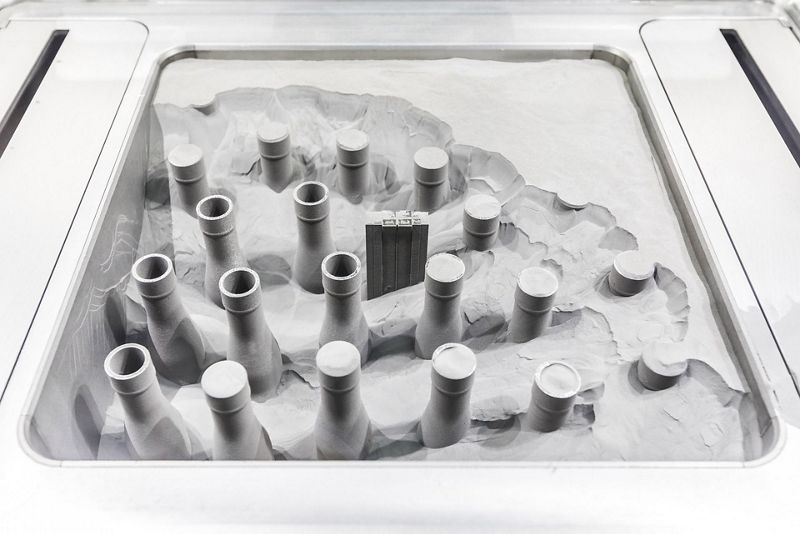
Metal 3D Printing
Timeless Material Meets Limitless Technology
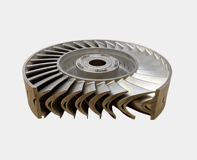
Direct Metal Laser Sintering (DMLS) is one of the few 3D printing technologies that directly create a metal part from its 3D computer model. DMLS shares the use of metal powders and lasers to print parts. This technology combines the design flexibility of 3D printing with the mechanical properties of metal. From tooling inserts with cooling channels to lightweight structures for aerospace, any application that involves complex metal parts potentially benefits from Metal 3D Printing.
-
Fully Functional Prototype
-
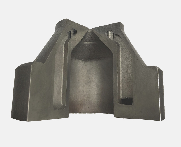
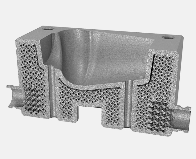
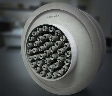
Conformal cooling channel in Injection molding dyes
-
Topology optimization
-
Heat exchanger and heat sinks
-
Complex assembly as a single part
Have any Questions or Suggestions? We would love to help you!
Technical Specifications
Build Size
- 10" x 10" x 10" (250 x 250 x 250 mm)
Standard Lead Time
- 5-7 working days
General Tolerances
- +/- 0.005” for the first inch is typical, plus +/- 0.002” for every inch thereafter
Layer Height
- .0012” - .0016" depending on material
Surface Roughness
- 150-400 µin Ra, depending on build orientation and material used for the build
Infill
- 100%
DMLS 3D Printing Materials
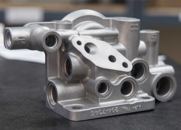
Aluminium
– Good strength and thermal properties with low weight
– Flexible post-processing possibilities
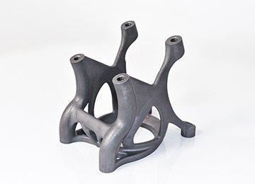
Stainless Steel
– Excellent strength, high ductility & good thermal properties
– Highly corrosion-resistant
Ready to get started on your DMLS 3D Printing Quote?
Free shipping on all 3D printing orders*
Advantages of DMLS 3D Printing
Printed parts with DMLS technology are durable, lightweight and precisely detailed.
- Print complex geometries with strong and durable components
- Rapid prototyping with high quality and high accuracy- ideal for functional testing
- Create complex shapes, intricate details and delicate features
- Reduce cost & development time by consolidating parts, no tooling required
- Build parts in a matter of hours
Applications of DMLS 3D Printing
Although the most popular industry that uses DMLS is the aerospace industry, other industries use the same process for different applications.
Aerospace
- Injectors
- Combustor liners
- Rocket engine manifolds
- Research efforts
- Functional prototypes
Medical
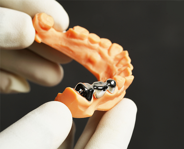
- Dental devices
- Surgical tools
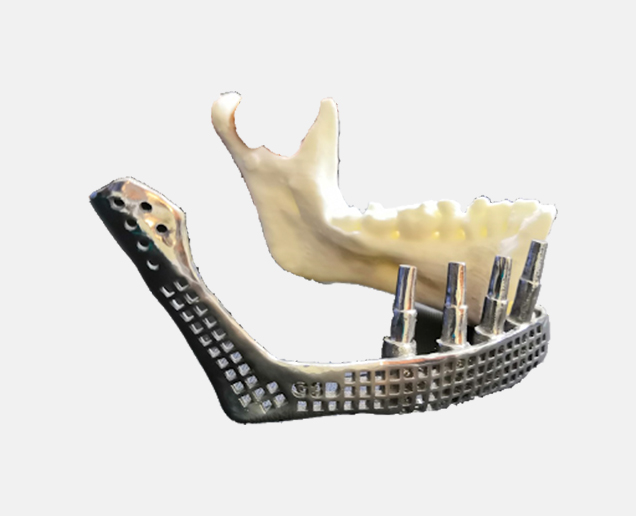
- Orthopedic implant devices/prototypes
- Educational models
- Training tools
Energy
- Rotors
- Stators
- Mud Motors
- Turbine prototyping and research
- Bridge applications
Industrial
- Prototype tooling
- Manufacturing fixtures
- Low volume production
Have any Questions or Suggestions? We would love to help you!
DMLS Design Guidelines
Wall thickness
- Minimum thickness of 0.4 mm
Pin Diameter
- Minimum is 1 mm
- If smaller diameter is needed, reduce contour sharpness
Escape holes
- Holes are needed on hollowed metal parts so unmelted powder gets properly removed
- Bore hole diameter between 2 and 5 mm is suggested
Support/Overhangs
- Support is necessary in all situations
Unsupported Walls
- 0.5 mm is the maximum length a cantilever-style overhanging surface can be
Aspect Ratio
- Maximum ratio is 8:1 Between the vertical print height and part section. This is yo stabilize the printed part on the build plate
Tolerances
- Part tolerance is ± 1mm -layer thickness in print direction
- 0.127 mm is attainable in the XY plane
Minimum Features
- 0.6 mm required
Embossed/Engraved Details
- 0.1 mm wide/high
Limitations of DMLS 3D Printing
As the cost is often higher with both machines and materials, using this technique is not often fit for producing high volume orders. Design also is a limitation when using DMLS. This is because not all applications designed when using traditional manufacturing can be converted to a additive manufacturing solution. More restrictions when using DMLS is product size. Most machines, even large machines, have a small build size volume. The average build volume size is 250 mm x 250 mm x 300 mm. Furthermore, machines are very complex to use, coming in industrial sizes and strict operating, material handling, post processing and maintenance procedures.
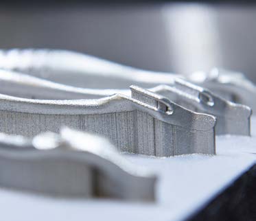
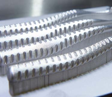
DMLS Post-Processing
The most frequently used post processing methods are the following;
- Surface treatment
- Support removal
- Heat treatment
- Machining
Have any Questions or Suggestions? We would love to help you!
How does Metal 3D Printing work?

The 3D model
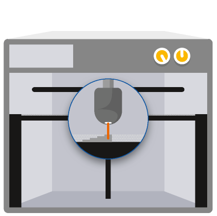
A laser melts metal particles together
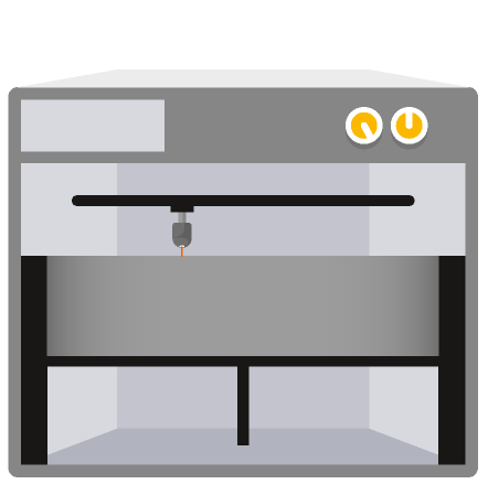
Successive layers of metal powder are spread on top, while a laser selectively binds particles to form the part and its support
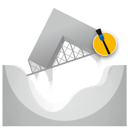
The loose powder is removed

The part undergoes heat treatment
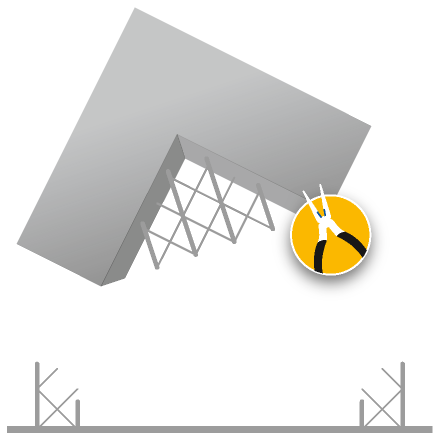
A laser melts metal particles together

The part is finished
