Selective Laser Sintering (SLS)
3D Printing
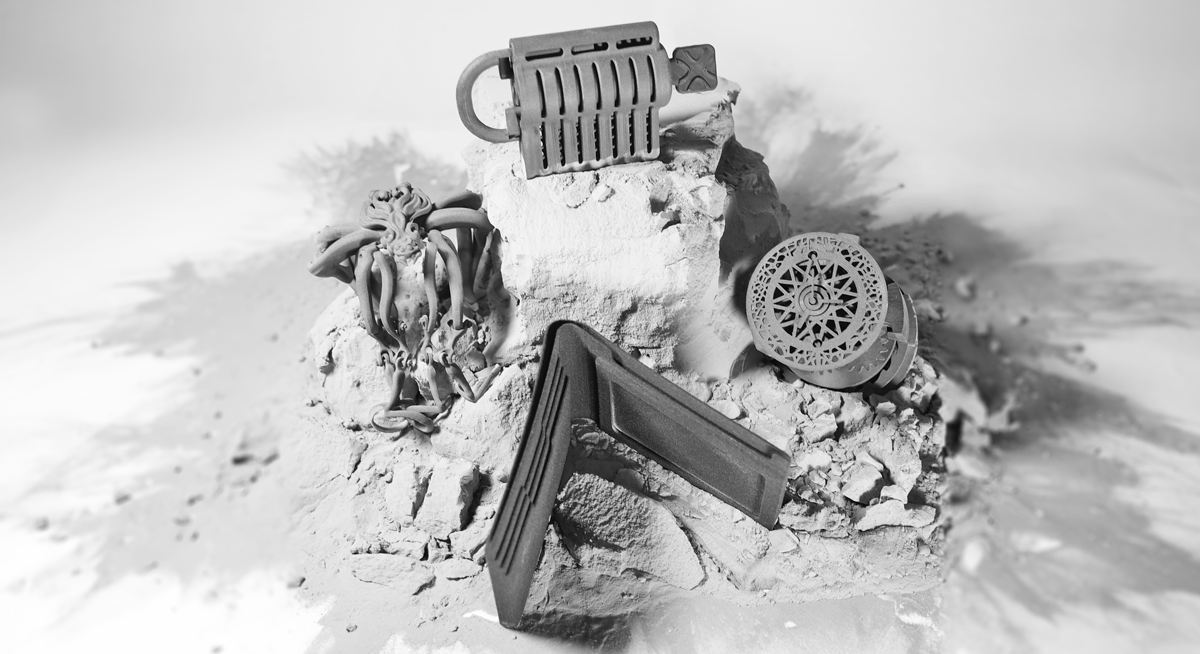
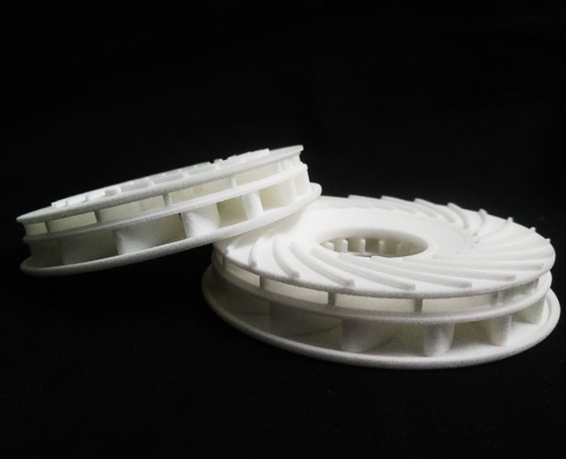
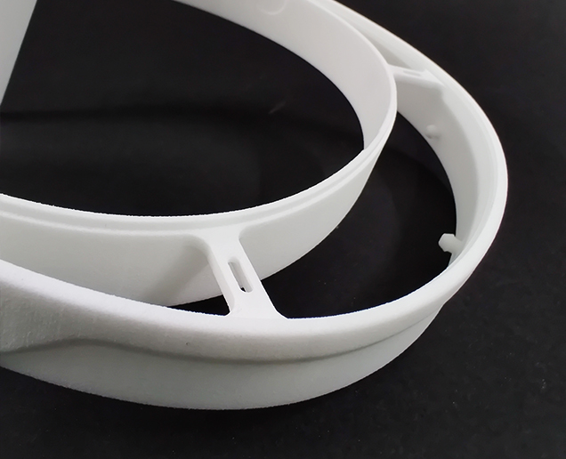
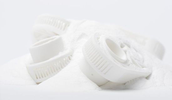
Laser Sintering, also known as Selective Laser Sintering (SLS), is among the most versatile and frequently used 3D printing technologies. As a self-supporting build methodology, SLS enables the production of complex geometries, such as monolithic designs, lightweight components, and mass-customized products that could not be manufactured in any other way.
Why Choose SLS?
Structures? Not in SLS 3D Printing!
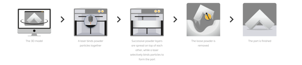
Selective Laser Sintering (SLS) 3D printers make use of a CO2 laser and a thermoplastic polymer powder to build parts. Because of the high power, the laser moves along a “point-to-point” pattern, solidifying the whole cross-sectional area of a layer. After the layer is complete, the re-coater deposits a new layer of powder and the build platform moves down one layer in height. The process is then repeated until the part is complete.
-
Low Volume Production
-
Prototypes with mechanical properties to rival those of injection-molded parts
-
Economical production of unique, complex designs built as one-off products or in small batches
-
Lightweight designs using complex lattice structures
Have any Questions or Suggestions? We would love to help you!
Technical Specification
Standard lead time
- Minimum of 4 working days, depending on part size, number of components and finishing degrees
- Minimum of 2 working days for parts with dimensions smaller than 200 x 100 x 100 mm
Standard accuracy
- ±0.3% (with a lower limit on ±0.3 mm)
Layer thickness
- 0.12 mm
Minimum wall thickness
- 1 mm, but living hinges are possible at 0.7 mm
Maximum build dimensions
- Dimensions are unlimited as components may be composed of several sub-parts. The build area of our largest machine is 350 x 350 x 600 mm
Surface structure
- Unfinished parts typically have a grainy surface but all kinds of fine finishes are possible. Laser-sintered parts can be sandblasted, colored/impregnated, painted, covered and coated
Materials
– Nylon Powder – polyamide 12 compound
– Strong & flexible plastic with excellent mechanical properties for fully functional parts.
PA-GF
– Polyamide Powder filled with glass particles
– Much higher thermal resistance (up to 100 °C) polyamide
– Lead time: 8 Working Days
– Maximum part dimensions: 630x330x550 mm
Ready to get started on your 3D printing quote?
Free shipping on all 3D printing orders*
SLS Design Guidelines

Wall Tickness
In 3D printing, wall thickness refers to the distance between one surface of your part and the opposite sheer surface. For PA 200, we recommend a minimum wall thickness of 1 mm but living hinges are possible at 0.3 mm. High wall thickness can give you a strong solid surface, while lower wall thickness can create a flexible and expandable surface. For example, thin surface walls are ideal when designing a spring that needs some suspension properties. This makes your part light and flexible. The opposite effect can be achieved by making your surface walls thicker.

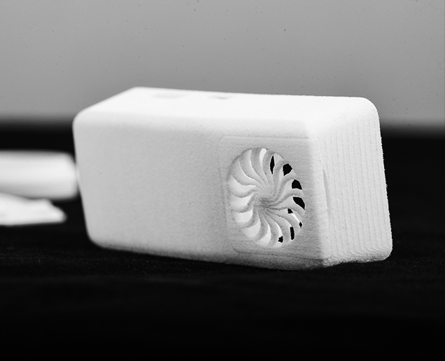
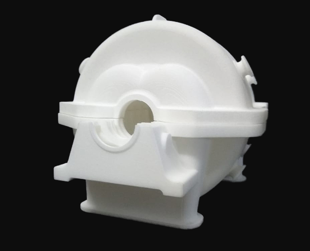
Hollowing
If possible, try to hollow out your part. This avoids deformation and discoloration during the printing process. You can either hollow out your part without a surface hole, which means that unsintered powder will remain trapped inside, or you can design a strategically placed hole (two would be even better) so that the unsintered powder can be easily removed after printing. If the part needs to be reclosed, design a lid with a diameter allowing for 0.5 mm play between the part and the lid.
If your part has walls thicker than 9 mm, our production team may hollow out the part to prevent deformation and discoloration. For parts with wall thickness higher than 20 mm wall thickness, this is done by default. In that case, the powder will stay trapped inside.
Warpage and Deformities

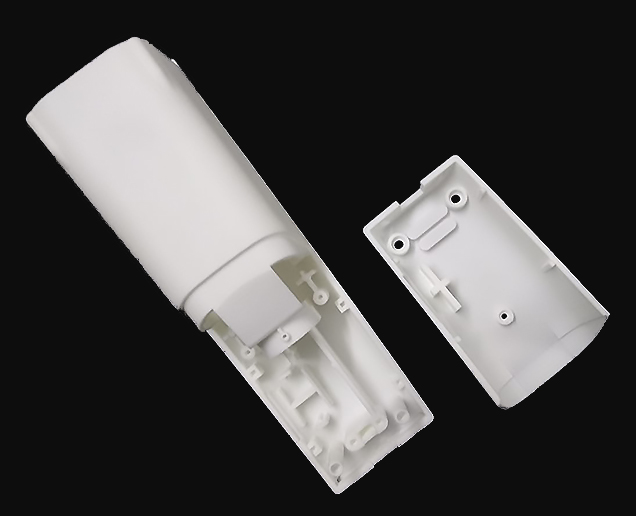
Interlocking or Moving Parts
It is possible to print interlocking and moving parts or single-build assemblies in PA 2200 (SLS). Parts that are printed together should have a minimum clearance of 0.5 – 0.6 mm. If you want to print a chain, spacing between your surfaces is crucial. The more space you can afford the better. The more complex your part is, the more difficult it becomes for us to evacuate un-sintered powder from the interior when the part is taken out of the 3D printer. Please get in touch with your local Customer Support Officer first before ordering parts of this kind to ensure printability and avoid disappointments.
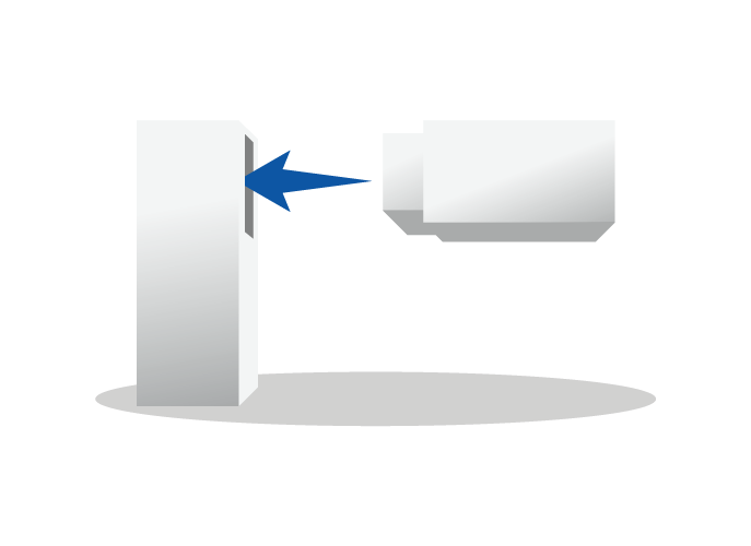
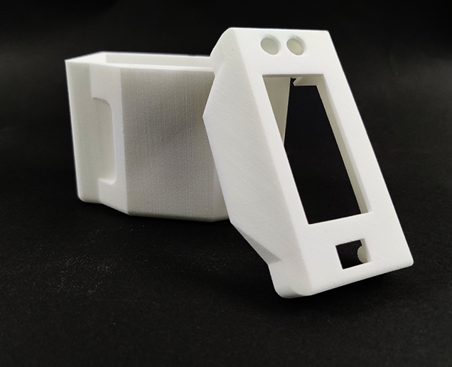
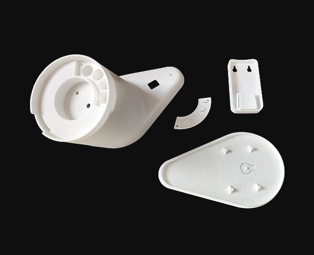
Assembly
When designing parts that need to be assembled, it’s important to maintain enough distance between the parts. A perfect fit in your CAD software does not necessarily ensure a perfect fit after printing because your software ignores the friction present in the real world. Therefore, always leave at least 0.6 mm between the different parts. For parts with large surfaces and wall thicknesses, you will need to maintain even more distance between the parts. In cases like these, please contact your local Customer Support Officer to check printability.
In order to help us print your parts with the best possible dimensions for assembly, please design your files with an orientation equal to the relative orientation of your parts in the final assembly.

Strength and Fragility
Several factors make it hard to fully predict the outcome of the polishing process. One of them is the geometry of your part, which can act differently each time it is put in the tumbler. In general, you should have wall thicknesses of at least 1 mm throughout your part. Although we carefully place and orientate your parts in our printers to minimize “weak points” created by the layered buildup of your part, certain elements of your design may be more sensitive to the impacts of the polishing stones than others. Therefore, we suggest adding some extra wall thickness if your design can allow for it. Smoothing is not advised if your part has tiny details like pins because they are likely to break off during the polishing process. The largest dimension of your part should not be more than 200 mm, as bigger parts can get stuck during the smoothing process. The smallest dimension should not be less than 30 mm, as smaller parts can break in the process.

Interior Polishing
The small size of the polishing stones means that they can easily get stuck inside small holes. Therefore, we recommend that any openings which need polishing should be larger than 6.5 mm in diameter. This helps prevent stones from getting stuck inside your model. Also, note that the inside of your model will always be less polished than the outside. In fact, your part will not be polished at all on the inside if the holes are smaller than 6.5 mm because the stones will not be able to enter.

Rounded Edges
If your part contains sharp edges, these will be rounded off. Rounded corners and smooth transitions between surfaces will have a higher degree of polishing than sharp edges.
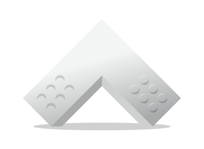
Embossed and Engraved Details
For engraved text or surface details, we recommend letters with a minimum line thickness of 1 mm, a depth of 1.5 mm, and an overall height of at least 4.5 mm. Embossed text or surface details should be thick enough that they will not break during production or transport. We recommend letters that have a line thickness of at least 0.8 mm, an overall height of at least 3 mm, and a depth of at least 0.8 mm.
File requirements
We accept file formats such as STL, 3DS, 3DM, OBJ, STP, SKP, SLDPRT, STEP, IGES, Parasolid.
Mail your design file to sales@voxelwerks.com with the above-mentioned format.
Have any Questions or Suggestions? We would love to help you!
Applications of SLS 3D Printing
SLS applications allow functional prototyping or large production parts in taxing environments. Prototypes with mechanical properties similar to injection-molded parts are used, as well as lightweight designs in complex lattice structures. Certain design applications for SLS below will mark several instructions that will ensure a better quality SLS part.
Application
Design
Axles
- Nylon provides smooth low friction mechanism for low load and velocity applications
- Surface clearance of 0.3 mm is recommended for running axles
- Powder must be removed to ensure smooth running shaft
- Escape holes with the minimum size of 3.5 mm diameter must be included wherever possible
- 2 mm between the running shaft axle and clearance shaft hole is required to allow for powder removal
Integrated Hinges
- Works well with SLS nylon when designed accurately
- Pocket the shape of a trapezoid accepts a semi-spherical ball
- This allows for low friction and decent stability
- 0.2 mm of space between the sphere and pocket is suggested with 0.3 mm clearance between every other gap
- 2 mm between the running shaft axle and clearance shaft hole is required to allow for powder removal
Tanks
- SLS nylon provides chemical resistance
- Executed in custom tank design
- Anything greater than 1 mm is required for the wall thickness
Threads
- SLS produces rough surfaces when increased friction connects the threaded SLS parts together
Living Hinges
- SLS is a printing method that produces functional living hinges
- Anneal the hinges by heating it up and flexing the hinge back and forth
- Hinges should be 0.3-0.8 mm thick and minimum 5 mm in length
Limitations of SLS 3D Printing
SLS applications allow functional prototyping or large production parts in taxing environments. Prototypes with mechanical properties similar to injection-molded parts are used, as well as lightweight designs in complex lattice structures. Certain design applications for SLS below will mark several instructions that will ensure a better quality SLS part.
Product Size
- The size of a part being printed is limited by the size of the nylon containers used in SLS machines
- Average build volumes = 300 mm x 300 mm x 300 mm
- Larger machines offer build volume of 700 mm x 380 mm x 580 mm
Consistency
- Because there are so many layers within printing SLS parts, variations between products may occur within the dimensions and surface quality
- Post processing steps are done manually
- Minor variations may occur such as small colour or coating variations
Surface Finish
- Grainy finish
- Post processing recommended
Benefits of SLS 3D Printing
Laser Sintering is a great option when the geometric complexity of a part makes it difficult to produce through other processes or when the anticipated production volume doesn’t justify the time & expense of tooling.
- Consistency & Reliability - Implementation of stringent, proprietary process controls and procedures for executing builds, maintaining equipment, and handling materials.
- Production Parts - SLS is an affordable means to build durable, stable production parts in low volume. Also effective for high volumes of components when designs are too complex for traditional manufacturing to execute
- Part Consolidation - With the ability to produce complex features, undercuts, and internal features with ease, SLS can consolidate what once was a multi-part assembly into one part. SLS eliminates the need for separate fasteners, mounting components, and adhesives.
SLS vs Injection Modeling
- Function
- Form
- Fit
Injection Molding
SLS
- Injection molding must be removed from a die
- Can not produce undercuts, negative drafts or interior features
- No removal of die required
- Can easily conduct undercuts, negative drafts and interior features
- Costly
- Terminates need for costly tooling
- More affordable for a small series production
- Has the ability to produce sharp edges and exact corners
- Can only produce parts that include a radius of ±0.4 mm at all corners and edges
- Keep in mind that a radius of 0.4 mm on a design will be printed as 0.4 mm
- Stress relief is not offered
- Natural radius offers some stress relief
- Areas of concern require a larger radius than 2 mm
Have any Questions or Suggestions? We would love to help you!
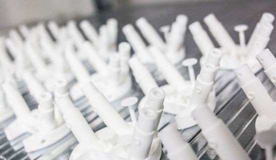
How Does Laser Sintering Work?
Laser Sintering is a laser-based technology that uses solid powder materials, typically plastics. A computer-controlled laser beam selectively binds together particles in the powder bed, by raising the powder temperature above the glass transition point after which adjacent particles flow together. As the powder is self-supporting, no support structures are necessary.